Two numbers decide most power-continuity arguments on a highway ETC project: how long the load runs without grid power, and how long it takes to switch over when the grid disappears. On the ETC gantry integrated intelligent cabinet, the first number is published as about 4.8 hours for one 100 Ah lithium iron phosphate set and 8 hours for two sets. Both figures describe a load level, an ageing state and an end-of-discharge condition the page does not spell out, so treat them as a design target for one reference duty rather than a runtime you can write into a bill of quantities for every gantry.
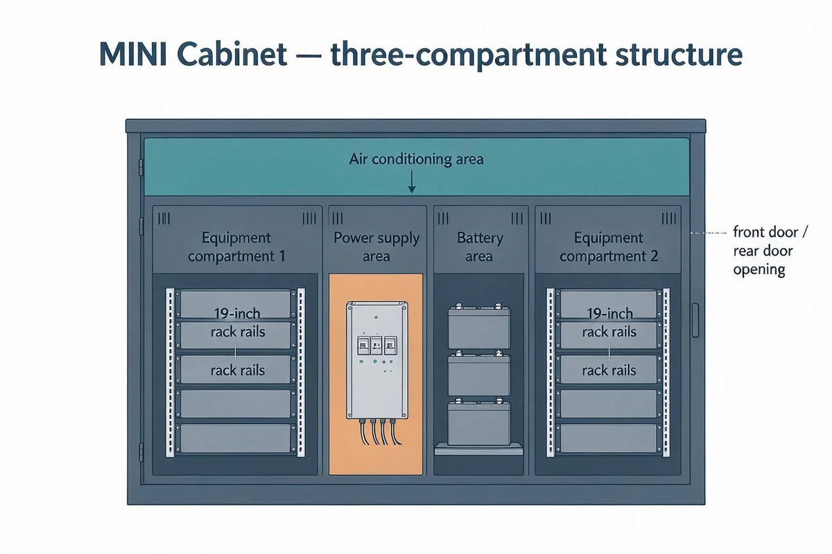
The cabinet is a 2200 x 800 x 1000 mm enclosure on an aluminium profile frame with composite panels, holding a 4U power distribution unit, two 3 kVA UPS units, a battery rack, a 1500 W AC air conditioner, a DC48V waterless air conditioner, a 24-core ODF, a 24-port gigabit PoE switch, a video capture device and a power and environment monitoring unit. What follows explains how those parts are meant to carry a toll transaction through an outage, where the runtime figure comes from, and what to record before a project accepts it.
What has to keep running, and for whom
An ETC gantry is a tolling point with no staffed booth. The roadside unit, the plate cameras and their fill lights, the encryption cards and the lane controller that writes the transaction record all sit on a crossbeam above a mainline carriageway. Nobody is at the site during a power failure, so the equipment has to finish the transactions it can still capture and hold its records until the network returns; otherwise the same journey can be billed twice or not at all. The PoE switch, 24-core ODF and 19-inch equipment space exist because the communications and tolling electronics live inside the cabinet, which puts the cabinet's own power chain on the tolling control path rather than in a utility role.
That framing sets the design question. Continuous tolling depends on three different things: enough independent sources to ride out a normal distribution fault, an instantaneous handover for the short interruptions, and enough stored energy for the long ones. The cabinet answers each one with different equipment, and no single number covers all three.
Two paths into the cabinet: mains, generator and two UPS
Inside the cabinet are main and standby power distribution units, and the dual incoming lines feed multiple outputs. The 4U distribution unit lists lightning protection and generator conversion, and its remark names the two inputs plainly: mains power and generator. The second path is therefore not a second utility feeder but an on-site generator connection. That still matters, because the two failure modes differ. A utility-side fault, a planned feeder outage or a lightning strike on the line is covered by the generator once it is coupled and running. A missing or failed generator is covered by the batteries alone.
Downstream of that, the feature copy describes two 3 kVA UPS units with pure sine wave output, zero-transfer technology and intelligent battery management, while the parameter table lists a single 3 kVA, 4U ISPS. Those are two different fields, and this article uses the two-unit figure because the supply architecture depends on it. Two 3 kVA modules give separate protected outputs rather than one 6 kVA block, so a failed module takes out its own group of loads and leaves the other group on line. Which device sits on which output is not stated, and it is the first thing to settle in a real design: putting the roadside unit and the lane controller on the same module gives up the benefit of splitting them.
What zero-transfer really buys
Transfer time is the gap between losing mains and having the load carried by stored energy. In an online, double-conversion UPS the batteries stay connected to the inverter, and that inverter has been feeding the load all along, so when the rectifier drops out there is no switch to throw. A standby or line-interactive unit instead moves the load onto its inverter after detecting the loss, and detection plus switching can take as long as 25 milliseconds. Both topologies end up on battery; only the second exposes the load to that gap.
Zero-transfer is therefore a property of the UPS output during a mains failure, not a promise that the cabinet sees no disturbance at all. Other events still produce a transient: a generator that couples late, a static bypass that engages because the inverter is overloaded, a battery string isolated for maintenance. On an online unit the output also holds a synthesised sine wave, which matters for switched-mode power supplies and for camera and fill-light drivers that react badly to stepped output. The question worth asking a supplier is narrower than the technology label: at what percentage of rated load does the unit stay on inverter, and where is the bypass threshold.
Where the 4.8-hour and 8-hour claims come from
A DC48V 100 Ah lithium iron phosphate set holds 4.8 kWh, and 4.8 kWh spread over 4.8 hours is an average DC load of roughly 1 kW. That is the reading to test against the site, because it makes the published duration a statement about one load level rather than about the cabinet's maximum draw.
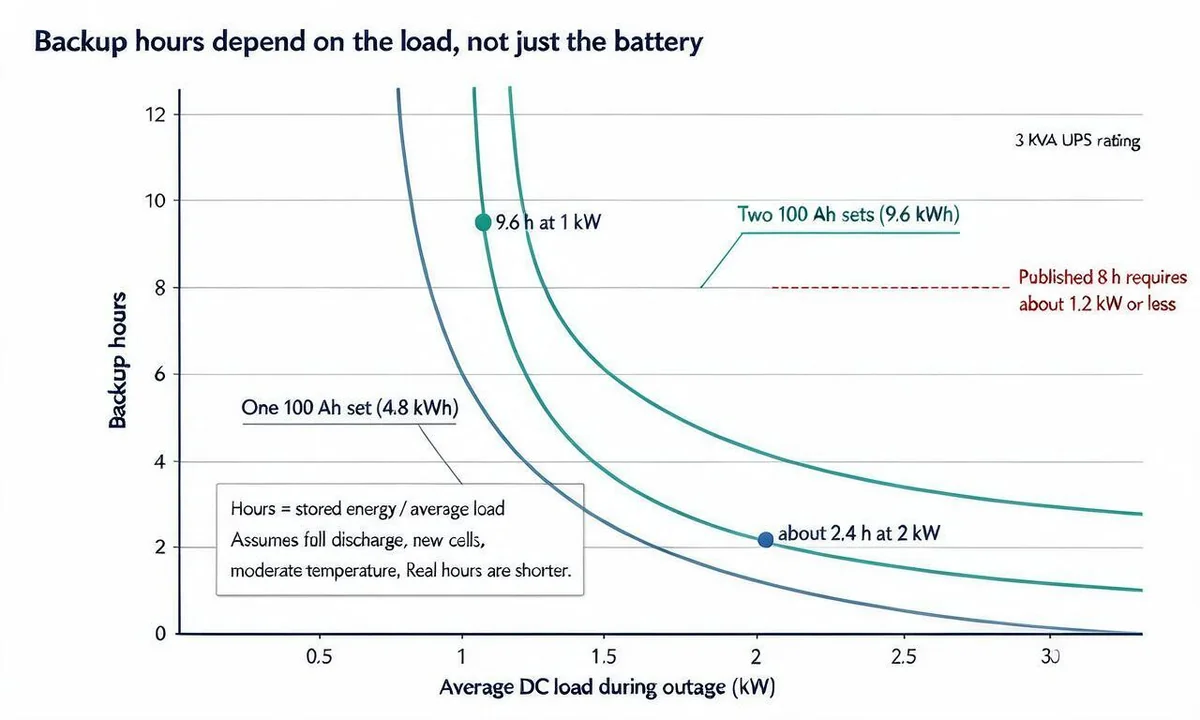
Run the arithmetic the other way and the ceiling appears. At the full 3 kVA rating of a UPS, one set holds about 1.6 hours and two sets about 3.2 hours, before conversion loss, derating and end-voltage margin. The 4.8 kWh figure is the outer bound of what one set holds; the 4.8-hour figure is what remains once the load has been chosen to fit inside it. A 100 Ah rating is also a reference value, since a cell delivers less than its nominal ampere-hours when it is discharged faster, when it is cold, and when it has aged beside a battery rack on an open gantry, which is why capacity is normally established by a discharge test rather than by reading a label. Whatever the chemistry, the number you can defend is the one measured at the load the site actually draws.
The step from one set to two holds a second clue. At a fixed load, twice the energy should roughly double the hours, which would put two sets near 9.6 hours. The page stops at 8. Either the two-set figure is rounded to a standard tender requirement, or the two-set case carries a heavier load, or a reserve is held back. All three are reasonable, but they describe different projects, and the page does not say which one it means. Read the pair as two separately stated claims, not a capacity curve.
The battery row itself reads 240 V 100 Ah while the feature text calls the same battery DC48V, with two sets listed and lead-acid as an option. A 240 V stack would hold far more energy than a 48 V pack of the same amperage, so the two descriptions cannot both feed the calculation. The 48 V reading is the one consistent with telecom practice, where a common 48 V battery plant is standard and the DC architecture skips the output inverter, which is also why a DC-fed cabinet can spend more of its stored energy on the load. Confirm the pack voltage and topology on the order documents before either number goes into a design.
Four variables that change the hours on a real gantry
Load, and what it actually is. Usable runtime is stored energy divided by the average DC load while the site is off grid. Count the roadside unit, the lane controller, the cameras, the fill lights when they fire, the PoE switch and the monitoring unit. Lights that draw in short bursts still add to the average, and a cabinet carrying cameras on the crossbeam carries their PoE budget too.
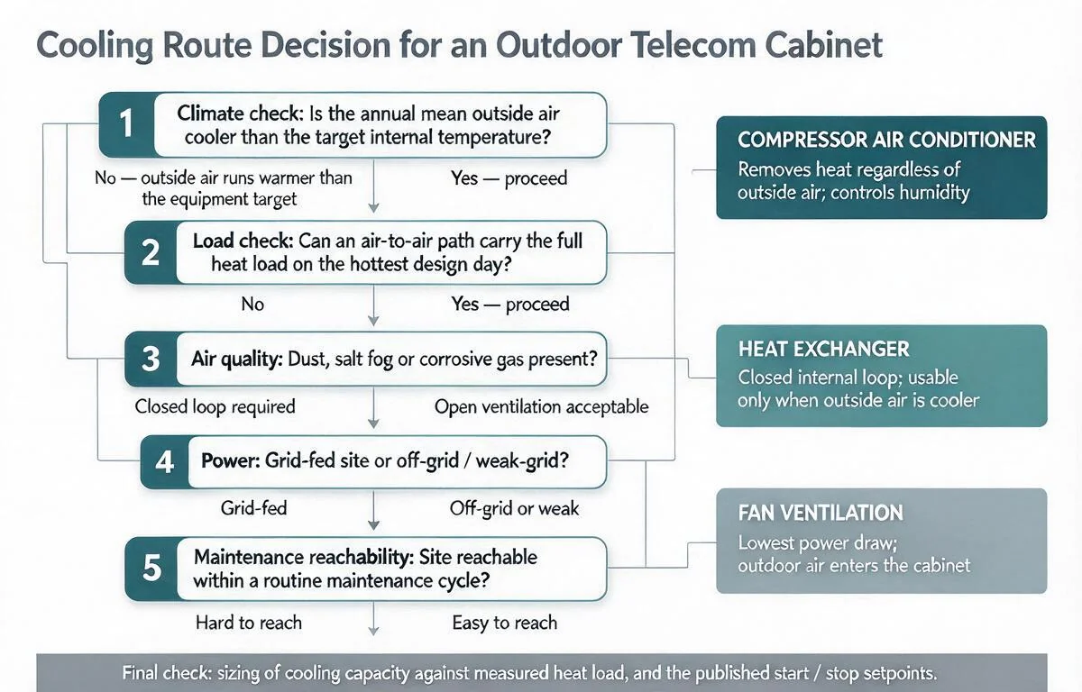
Whether the air conditioner keeps running. The table lists a 1500 W AC air conditioner while the feature copy describes a separate DC48V waterless unit. A compressor still cooling during an outage is a large continuous load against a 4.8 kWh pack, and the published hours almost certainly exclude it. Whether the air conditioner is shed, held at a higher set point or left running is a control decision that moves the runtime more than any battery option, so record it at design stage rather than leaving it to commissioning. How the cabinet manages that heat at all is covered in choosing between fan, heat exchanger and air conditioner.
Temperature and age of the battery. The page credits the lithium iron phosphate chemistry with high-temperature tolerance and long life. Both help on an unshaded gantry, but they set the slow drift of capacity over the asset's life rather than adding hours on day one, so plan for the runtime at the end of the service interval, not at the factory test.
Where the discharge stops. A UPS protects itself and its batteries by ending the discharge at a set voltage, and the energy below that point is not available to the load. Defining the hours as the time to cutoff, not to total exhaustion, is what makes a runtime figure repeatable.
Writing a runtime that survives an inspection
China's Ministry of Transport inspection procedure for ETC gantry systems and key equipment makes the backup-power claim checkable. Its quality inspection table for supply and distribution carries three separate scored items: backup power redundant operation, backup power switching time and backup power supply duration, alongside items for the cabinet's 19-inch installation, outdoor air conditioner, environmental monitoring, anti-theft and access control, cabinet lighting, fire alarm and mobile generator power interface. The same procedure inspects system-level main-standby switching, self recovery, offline operation and data retransmission, and expects operating checks at intervals no longer than six months.
The procedure tells you that all three backup-power items will be inspected; it does not hand you a number, so the requirement stays a project decision. A defensible statement has the same shape on any gantry: a measured DC load at the site, the battery configuration and cutoff voltage, the resulting hours, one stated assumption about air conditioner operation during the outage, and the discharge test that will confirm it. At an assumed 800 W average DC load, one 4.8 kWh set covers about 6 hours and two sets about 12 hours before derating, using the same arithmetic as the published figures; at 1 kW the same packs give about 4.8 and 9.6 hours.
The switch-over item is the easier one to close. Because the online UPS keeps the load on its inverter through a mains failure, the switching time that matters in practice is the generator handover, not the UPS. Record what the load sees between the mains trip and the generator pick-up, including how long the generator takes to start and accept load and whether the UPS rides through it on battery. A timed test that logs the transfer is the evidence a reviewer will ask for.
Redundancy is inspected as behaviour, not as a label. With two UPS modules, the test is whether the load on one module survives the other being switched off, and whether that trigger reaches an operator. The monitoring unit detects cabinet conditions and equipment status and supports remote control, with multiple DI/DO points including water immersion, temperature and humidity, and smoke detection. Setting the battery-voltage and air-conditioner alarm thresholds before the discharge test is what turns a monitoring screen into a signal that survives an outage.
What to settle with the supplier
Ask for the load table behind the 4.8-hour and 8-hour statements, and for the cutoff that defines their end. Ask which devices sit on each UPS output, whether the air conditioner is included in the outage load, and what pack voltage stands behind the 48 V and 240 V descriptions. If the answer is a data sheet figure rather than a site calculation, the runtime is still a target, and the first discharge test at commissioning is what turns it into a number your project can defend.
——END——